Forward Error Correction (FEC) is a widely used method to limit the amount of data retransmissions in noisy communication channels. To avoid resending data, the receiver of that data will attempt to correct bit errors that have occurred through the use of redundant data bits. If the errors can be corrected, then no retransmission is required, greatly reducing send time. FECs provide an interesting angle of covert transmission that, to my best knowledge, has not been explored by the academic community. As bits are corrected by the receiver, it is theoretically possible to inject a covert message into the encoded data prior to transmission, to be intercepted by a third party during travel. The covert message could then be extracted by the third party with little difficulty. The covert message, when received by the intended receiver, would be treated as bit errors and corrected, allowing for uncorrupted overt data.
The LTE standard has shown itself to be an ideal platform for a proof of concept. LTE uses turbo coding as its FEC method of choice, with well defined blocks of how data is manipulated, sent, received, and decoded. Additionally, much of the work on LTE covert channels has been done in the packet layers, with very little attention being paid to the physical layer of the system.
Research Questions
This research seeks to answer several questions: 1. Is a forward error correction covert channel within the LTE spec possible? 2. What would the theoretical bit rate of this channel be? What would be the effect on the overt data at the receiver? 3. How detectable is this channel?
LTE Basics
LTE sending and receiving is split into a number of well defined steps. Data transmission goes through two channels: the Downlink Shared Channel (DL-SCH) and the Physical Downlink Shared Channel (PDSCH). It is the job of the DL-SCH to prepare data for modulation. MATLAB provides an excellent image to represent the high level process.
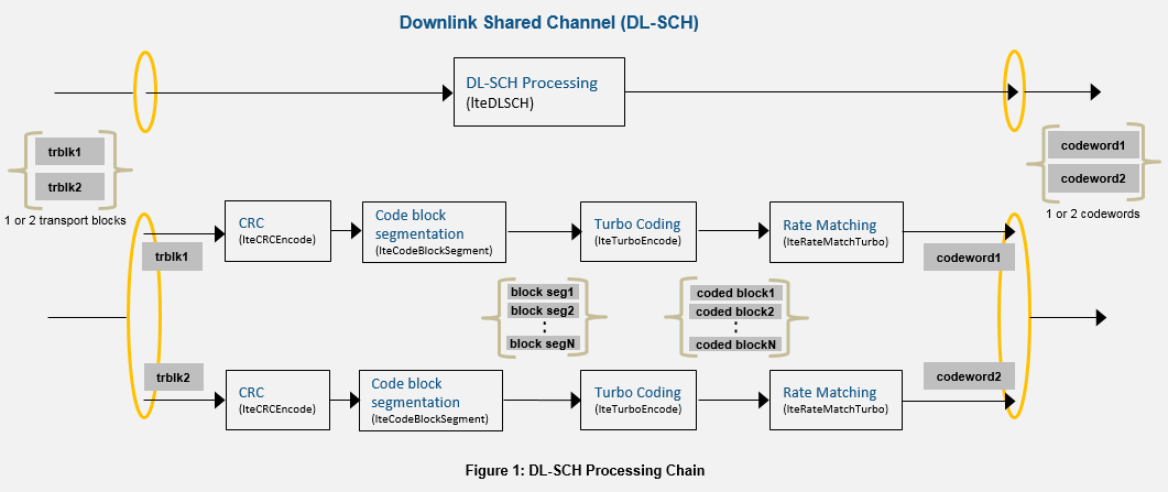
The very first thing that happens is one or two transport blocks are received by the DL-SCH. A transport block is data from the upper layer passed down to the physical layer. The number of transport blocks received corresponds to the transmission mode. If the transmission mode is Single Input Single Output (SISO), there would be one transport block. If the mode is Multiple Input Multiple Output (MIMO) there would be two or more transport blocks. The size of the transport block is determined by the modulation and coding schemes. Each transport block has its CRC calculated and is then segmented. The turbo encoder can only ingest data of specific sizes, requiring data segmentation before hand. The block segments are then encoded, which will be covered in the next section. After turbo encoding, the coded blocks are rate matched. Rate matching allows for a steady and controllable rate of data transmission. It also interleaves, or mixes up, the order of data. Data errors tend to occur in bursts. By mixing up the data, bit errors can be interspersed throughout the data, rather than in chunks, allowing for error correction.
Coded blocks are then passed to the PDSCH, which modulates and transmits the data. Once more, MATLAB provides an excellent image.
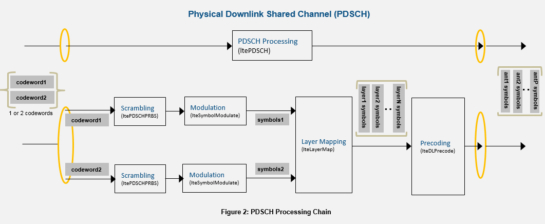
Coded data is first scrambled through a scrambler. Scrambling has several functions: makes data harder to read by unintended recipients, gives data a unique signature to aid in identifying the sender, can be used as analog encryption, and removes long runs of zeros in the signal. Scrambling XORs data with a pseudo random sequence. Further information on the scrambler will be covered later. At this point data is modulated, most likely with some variation of QAM, mapped to specific RX antennas (layer mapping & precoding), and is transmitted.
Turbo Coding Basics
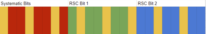
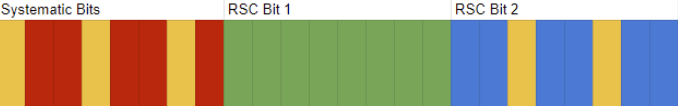
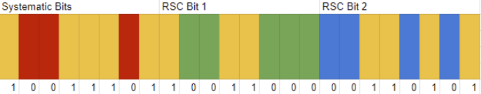
A Turbo Code is a forward error correcting code. The sender will encode the data, and the receiver is able to use this encoded information to discover and correct bit errors that occurred in transmission. The LTE Turbo Encoder takes one bit in and outputs three bits. The first bit is the systematic bit, this is the original data bit. The second bit is from a recursive systematic convolutional (RSC) code, calculated on the original order of the transmitted data. The third bit is also from a RSC, but this time it has been calculated from some permutation of the original data. After encoding, the bits will be organized in a concatenated block form, [Xk, Zk, Z'k], where Xk is all of the systematic bits, Zk is all of the first RSC bits, and Z'k is all of the second RSC bits. All three blocks are naturally of equal length. These bits are then processed, scrambled, modulated, and transmitted.
At the receiver, the bits are descrambled and demodulated. The demodulator is either going to return hard or soft data points. With hard data points, the actual binary data will be returned. But this is not very accurate. Channels are noisy, and the demodulator making definite decisions on what a bit is can lead to high rates of inaccuracy. Instead the demodulator will return a soft data point, a guess of what the bit is. For LTE this takes the form of a log likelihood ratio (LLR). A LLR helps make a decision about the validity of the received data and is roughly defined as the log of the resultant of the probability of a one occurring, divided by the probability of a zero occurring. A negative LLR indicates a likely zero bit, while a positive LLR indicates a likely one bit. A LLR value of zero is indeterminate. So the input to the Turbo Decoder is [LLR(Xk), LLR(Zk), LLR(Z'k)]. The Turbo Decoder will then use these LLRs to make a hard decision on what a bit actually is. There are a number of methods of making a hard decision. A popular one is the Viterbi Algorithm, which can be roughly summed up as "given a sequence of past bits, what is the probability of the nth bit in that sequence being a one or zero". With the hard decision made, the receiver can decide if it needs to ask for a retransmission of data.
Test Environment
RF equipment is expensive, easily running into the thousands of dollars. Instead, this project was done in MATLAB's LTE Toolbox, which is also expensive, but a license was available through school. The LTE Toolbox provides all the necessary functions to complete a LTE simulation. MATLAB's documentation even includes a basic implementation of the uplink and downlink. Several additions were made to this code: an informed uplink to intercept and extract covert messages, several methods of injecting covert messages into outgoing transmissions, and several statistics tracking and plotting functions.
Covert Message Embedding
Choosing the correct spot to embed the covert data is of the upmost importance, with specific spots offering different benefits and weaknesses.
The first obvious spot is after the encoder, but before rate matching and data interleaving. Covert data would be interleaved, spreading the message out over the bit stream. During testing however, it was found that rate recovery on the demodulator regularly yielded indeterminate LLR values for an unknown reason, resulting in useless data and requiring a retransmission. Not ideal.
The second possible spot is after rate matching and data interleaving. In this location the covert message can either mimic a burst error or be spread out throughout an outgoing message. Since the embedding is after interleaving, there is less data processing that needs to be done by the informed receiver. However, the informed receiver would need to know the Radio Network Temporary Identifier for the scrambler, which is covered the the Scrambling and Descrambling section.
The third spot is embedding after the scrambler, which is also not an ideal location. One of the functions of scrambling is to provide a unique signature for the uplink to identify handsets. Embedding here could ruin the identifiability of the signal, not to mention it would be embedding into an analog rather than digital stream.
The easiest and most practical solution was to go with the second location, embedding after rate matching and data interleaving. This spot allowed for the best chance of data retrieval with minimal corruption of the overt data. But how should this data be embedded? Should it try to mimic a burst error to make use the burst error defenses that LTE employs? Is replacing one type of RSC bit better than another? To attempt to test these cases, three different embedding methods were utilized, detailed below.
N-Bit Skip Embedding
In this method, every Nth bit is replaced with a covert data bit. Systematic bits and RSC bits can and will be overwritten. Small values of N are more similar to burst errors, and large values of N reflect a noisy channel.
Chunk Skipping
This technique seeks to avoid overwriting specific types of bits, with the rest of the bits being embedded utilizing N-bit skipping. Leaving one type of bit intact could potentially have a positive benefit on how long the covert message could be before uncorrectable bit errors are introduced.
LFSR Pseudo Random Embedding
This final method used a linear shift feedback register to embed into the sequence pseudo randomly. This is to simulate random noise in a channel.
Scrambling and Descrambling
As stated earlier, the scrambler creates a pseudo random sequence to XOR with the outgoing data transmission. The algorithm that creates this sequence uses the Radio Network Temporary Identifier (RNTI) as a seed. The RNTI is a well defined 16-bit value used to uniquely identify handsets to the receiving downlink and is exchanged during a LTE handshake. It is important to note that the scrambling sequence is not cryptographically secure. If an attacker intercepts the RNTI, the same scrambling sequence can be generated.
Testing Methodology
The effectiveness of the covert channel was measured by the length of the covert message versus overt errors and the bit error rate at the uninformed receiver. The Overt Error is defined as the number of bits the turbo decoder fails to correct after decoding the transmission. The Bit Error Rate (BER) is defined as the number of bits that change between Turbo Encoding and Decoding. Beyond the specified research questions, these tests sought to answer several questions:
- What is the maximum possible message length that can be corrected out at the uninformed receiver?
- Can an informed receiver successfully collect the covert message?
Using MATLAB, a number of possible scenarios were tested, systematically modifying length, number of bits skipped, and how often bits were skipped. The overt and covert messages were randomly generated each test, with equal probability between zero and one bits. Each overt message was two transport blocks, each being 11448 bits in length.
Results
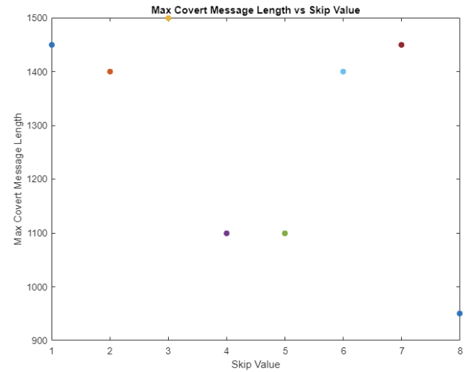
N-Bit Skip Embedding
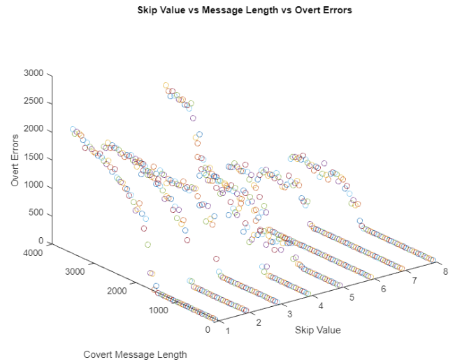
This test used possible skip values of one through eight, with a maximum potential message length of 2000 bits, and the message length being increased by 50 bits for each test. The largest covert message before decoding errors occurred on the uninformed receiver was 1500 bits with a skip value of three. Noticeably, increasing the number of skipped values did not result in an increase in covert message length.
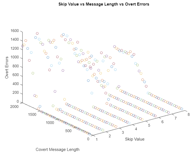
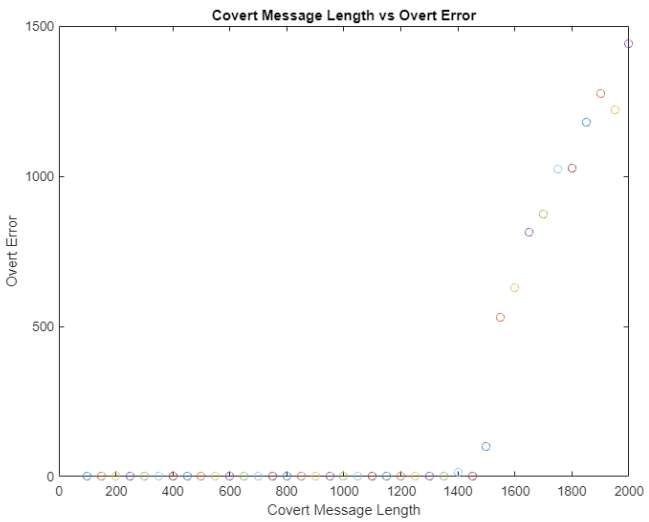
Looking at the skip value, message length, and overt errors all together, it can be seen once errors started occurring, they increased rapidly.
Chunk Skipping
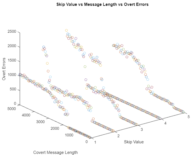
For chunk skipping, a maximum potential message length of 3500 bits was used, incremented by 50 bits each round. A value of 1 to 8 was used for the skipping. Regardless of whether the systematic bits or either of the RSC chunks were skipped, the results were roughly the name. The following graphs detail the first RSC bit chunks being skipped. With a N-bit skipping value of 6, the maximum covert message length was around 2600 bits.
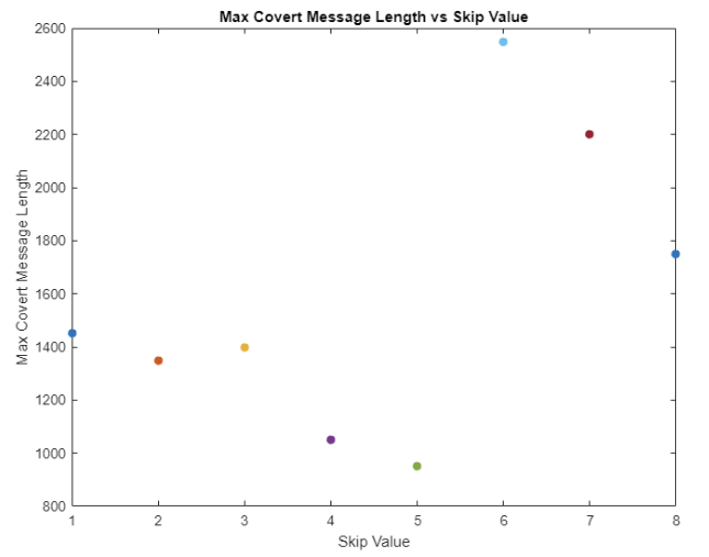
One thing of note is once overt errors started occurring, they either quickly leveled out or followed a logarithmic curve as message length increased in most cases.
A variation of this method resulted in the best case observed out of all the tested methods. In this case, only the first chunk of systematic bits were skipped, with the rest of the data being embedded using N-bit skipping. This resulted in a maximum covert message length of 4000 bits with a skip value of four.
LFSR Pseudo Random Embedding
For LFSR pseudo random embedding, three different sequences were tried with period lengths of 8191, 4095, and 511. A maximum potential length of 2000 bits was used, with each test incrementing the length by 50 bits. All three LFSR schemes maxed out around 1400 bits before overt errors were introduced.
Bit Error Rate
A good BER is very, very small. 10-9 is cited by many as the bare minimum for an acceptable BER. For the uninformed receiver, the BER depended on where the it is measured. Measuring the BER before decoding is not possible unless the receiver knew the message beforehand. If the turbo decoder outputted the number of corrected bits, the BER would be one to one with the number of embedded bits. But if the BER is measured after the turbo decoder, the BER would be in line with the number of introduced overt errors, with a best case of zero in a noiseless environment.
Further Discussion
This research showed, at the very least, forward error correcting codes in LTE could work as an alternate data channel. Depending on the scenario employed, it could also work as a covert data channel depending on where the BER is measured and whether or not that value is even paid attention to. As for the best methods, unsurprisingly, mimicking burst errors proved to be the most effective, considering LTE and turbo codes are designed to minimize their effect.
The real question is, how could this channel be used outside of an academic setting. Turbo codes are designed to be implemented at the hardware level, in the FPGA. The ability to inject covert messages into an encoded message would require an attack of quite a bit of sophistication. An interesting academic idea to be sure, but no immediately apparent real world application.
Conclusions
This research concluded with the successful covert transmission of a maximum of 4000 bits in two code blocks in a simulated LTE environment by injecting covert data into outgoing turbo encoded data. In most tested scenarios, a maximum covert message length of between 1200 and 1500 bits was measured. For these optimal message lengths, the uninformed receiver fully corrected the data, removing the covert message and leaving the the uninformed receiver unaware of any covert data transmission.
Future Work
Future research seeks to conduct the covert channel in a more realistic environment utilizing srsRAN or another LTE simulator. Additional research into other platforms utilizing forward error correcting codes is desired as well.
References
- [1]DL-SCH Processing Chain. MathWorks.
- [2]PDSCH Processing Chain. MathWorks.